Polar and Linear Planimeters
The main working parts of polar and linear planimeters
are the same. Each has a rod, called the tracer arm, one
end
of which is the tracing point T, and a wheel attached to the
rod
with its axis parallel to the rod. A scale attached to the wheel
records how much the wheel turns.
Polar Planimeter 
 Linear
Planimeter
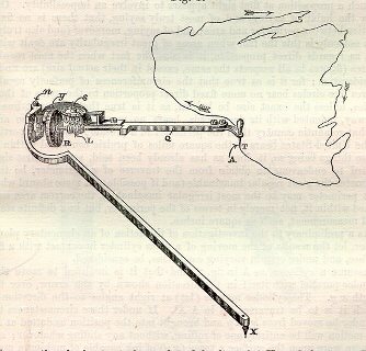
The two planimeters differ in the movement of the end of the tracer arm
opposite the tracer point. In the linear planimeter, that end is
restricted to move along a straight line. The drawing suggests
that
it runs along a track, but a more common way to cause this motion is to
have this end attached to a set of wheels that are fixed to an axis so
that the wheels turn together. In the polar planimeter, the end
opposite
the tracer point is restricted to move along a circle. This is
done
by making that point the hinge between the tracer arm and a secondary
arm,
one end of which (the pole) is fixed.
Linear
Planimeter
The two planimeters differ in the movement of the end of the tracer arm
opposite the tracer point. In the linear planimeter, that end is
restricted to move along a straight line. The drawing suggests
that
it runs along a track, but a more common way to cause this motion is to
have this end attached to a set of wheels that are fixed to an axis so
that the wheels turn together. In the polar planimeter, the end
opposite
the tracer point is restricted to move along a circle. This is
done
by making that point the hinge between the tracer arm and a secondary
arm,
one end of which (the pole) is fixed.
The original polar planimeter was invented in 1854 by Jacob
Amsler, a Swiss mathematician and inventor of many measuring
instruments.
It was so much simpler, easier to use, and more accurate than previously
invented planimeters that the latter quickly became obsolete.
Further modifications of his basic design were made only to improve its
accuracy. The linear planimeter works on the same basic principle
as the polar planimeter, and is simply a variation that allows the
areas
of long, skinny regions to be measured.
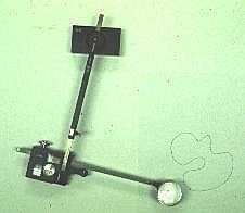
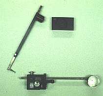
Here are some pictures of a
Keuffel
& Esser polar planimeter I have (model 620015). This was made by the German
company Haff in about 1970.
The picture on the left shows the planimeter ready to measure the area
of a region. On the right is a disassembled view. The
tracer
point is equipped with a magnifying glass to make it easier follow the
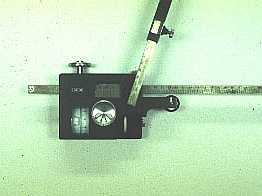
curve. The box at the left end of the tracer arm is a carriage
containing
the wheel and the counter with its scale. The wheel rests lightly
on the paper and can roll when the tracer point is moved. The
pole
is at the top and is held in place by a weighted block that allows the
pole arm to pivot.
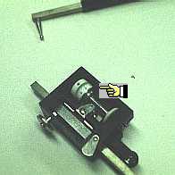
The axis of the wheel is easily seen on the underside of the
carriage.
The wheel itself (indicated by the pointer) is a steel disk attached
directly
to the cylinder with the scale. The plastic wheel on the same
axis
that is visible in both pictures is slightly smaller than the steel one
and does not contact the paper. It is used to set the scale to
zero.
This planimeter is on permanent loan from a member our biology
department.
If you are looking for a planimeter, good places to check are physics,
chemistry, and engineering departments. They are almost always
available
at reasonable prices on eBay.
How Polar and
Linear
Planimeters are Used
These planimeters are used by
moving the tracer
point around the boundary of the region being measured. As the
tracer
point moves the wheel partially rolls and partially slides on the
paper,
recording its motion perpendicular to the tracer arm. It turns
out
that when the tracer point returns to the point where it started, the
net
roll of the wheel is proportional to the area of the region. If a
scale attached to the wheel is calibrated appropriately, the area can
be
read from the scale.
How Planimeters Work