Tracing a Region with a Planimeter to Prove the Isoperimetric
Inequality
We need to trace the boundary of the
region with a planimeter in such a way that
- The tracer point goes around
the boundary of the region as usual,
- The curve followed by the opposite end of the tracer arm encloses no area, and
- The planimeter
makes a full rotation in the process.
Two methods are shown to do this. Each method consists of four steps:
- Determining the path of the opposite end of the tracer arm,
- Determining the "extreme points" on the boundary,
- Determining the length of the planimeter, and
- Determining the motion of the planimeter.
Note: For reasons that are described elsewhere, the integrating wheel
of the planimeter (shown in red below) is taken to be at the tracing point.
Linear Track Method
|
The track is taken to be a line through the region such that the
points on the boundary curve farthest from the line and on opposite sides of the
line are the same distance from the line. These points are the extreme points.
(If there are more than two points that are this distance from the line, choose
one on each side.)
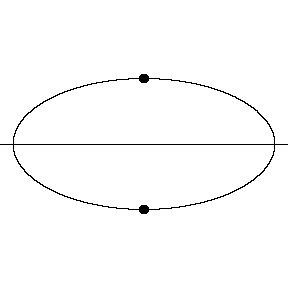
In an elliptical region, the line can be one of the axes, in
which case the extreme points are the opposite vertices. |
 |
|
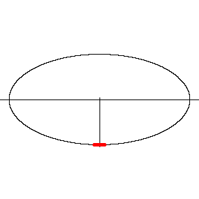
The length of the planimeter is the distance from the
line to the extreme points.
Click on the image to see the motion of the planimeter. The
motion pauses at the extreme points.
|
 |
Example with the same ellipse, but a
different line.
More Examples: Curve 1
Curve 2 Curve 2, Second Example
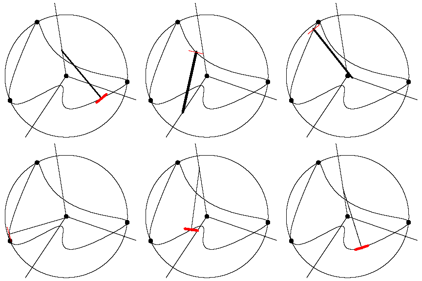
Circumscribing Circle Method
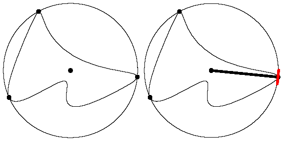
| Start by considering the smallest circle that contains the
region, the circumscribing circle. The length of the planimeter is
taken to be the radius of this circle. The extreme points of the boundary of
the region are those that are on the circle. |
 |
| Determining the path that the opposite end of the tracer arm
will follow is a bit technical.
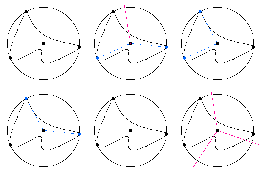
Consider a pair of extreme points for which the
arc of the boundary between them lies strictly inside the circle. We call
these consecutive extreme points -- they will determine a ray that will be
part of the path. The points form an angle with the center of the circle as
its vertex (blue dashes). The desired ray is the one opposite the angle
bisector of this angle (red).
The path followed by the opposite end of the
tracer arm is the union of rays determined from pairs of extreme points in
this way. In this example there are three such rays (red). |
|
|
The tracer arm moves in such a way that when the tracer
point (also the location of the wheel) is on the arc between consecutive
extreme points, the opposite end is on the ray determined by that pair of
extreme points.
Another example |
|


